
Juniper SRXのHA設定方法
ESXiでvSRXのHA構成環境を構築したので、Juniper SRXのHA(Chassis Cluster)設定方法を解説していきます。
自身の検証環境は以下のとおりです。
- Windows PCのVM Workstation Player上で、ESXiを構築し、vSRXを構築する
- Windows PCのバージョンは、Windows 11
- VM Workstation Playerのバージョンは、VMware Workstation Player 17.0.2
- ESXiのバージョンは、VMware vSphere Hypervisor 7.0
- vSRXのバージョンは、23.1R.8
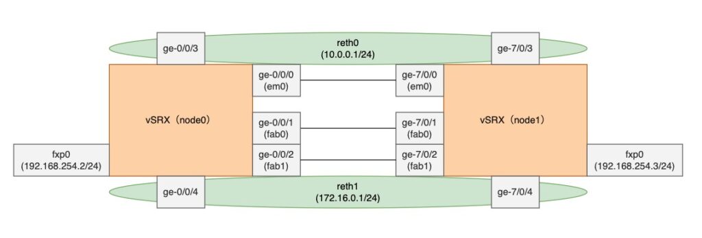
構成としてはvSRXのActive StandbyのHA構成を想定しています。
vSRXの構築
ESXiを構築
VM Workstation Player上で、ESXiを構築する方法は別記事で紹介しているので、ぜひ参考にしてください。

ovaファイルをダウンロード
まずは、vSRXのovaファイルをダウンロードします。ダウンロードには、Juniperアカウントが必要になるので作成しましょう。Juniperのアカウント作成方法は別記事で紹介しています。
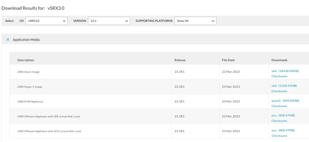
公式サイトからovaファイルをダウンロードします。2023年6月時点では、vSRX3.0が最新だったので利用しました。
「vSRX VMware Appliance with IDE virtual disk (.ova)」を選択して、ダウンロードします。
ライセンスへの同意が求められるので「I Agree」で同意します。
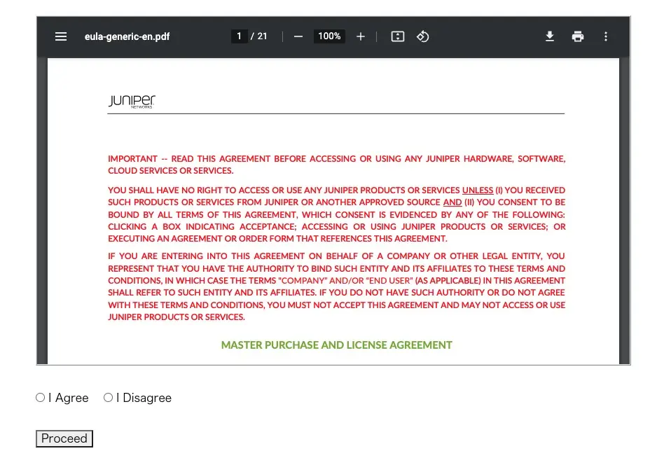
リンクからovaファイルをダウンロードできます。

ESXiでvSRXをインストール
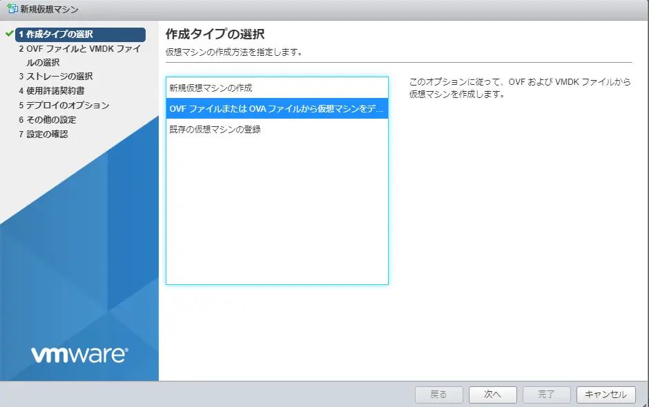
ESXiでvSRXを構築していきます。ESXiで「仮想マシンの作成/登録」をクリックします。
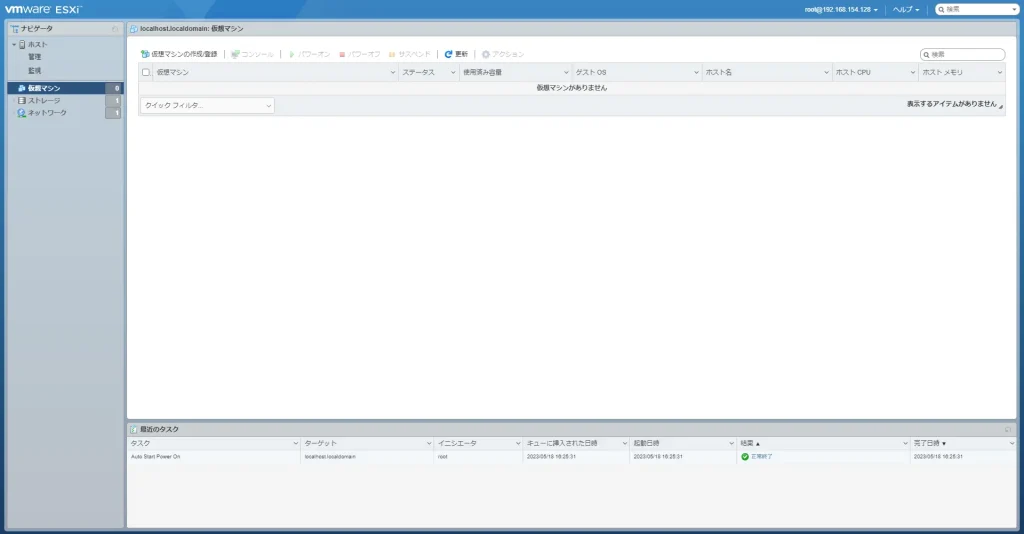
OVAファイルから仮想マシンをデプロイを選択します。
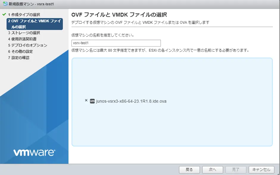
仮想マシンの名前を設定し、ダウンロードしたvSRXのovaファイルをアップロードします。
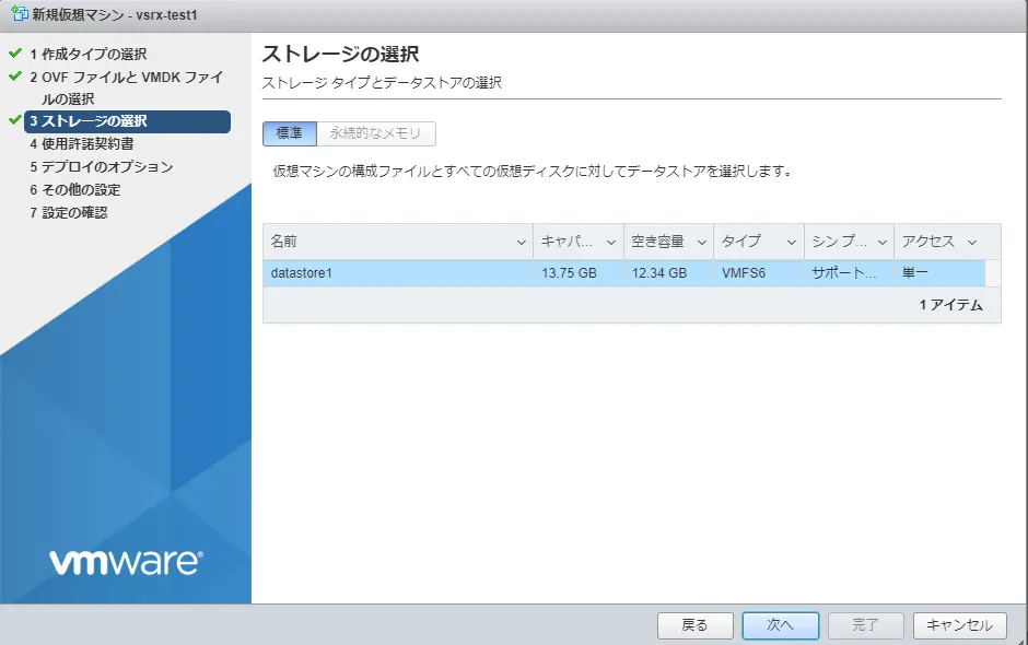
ストレージを選択します。設定はデフォルトです。
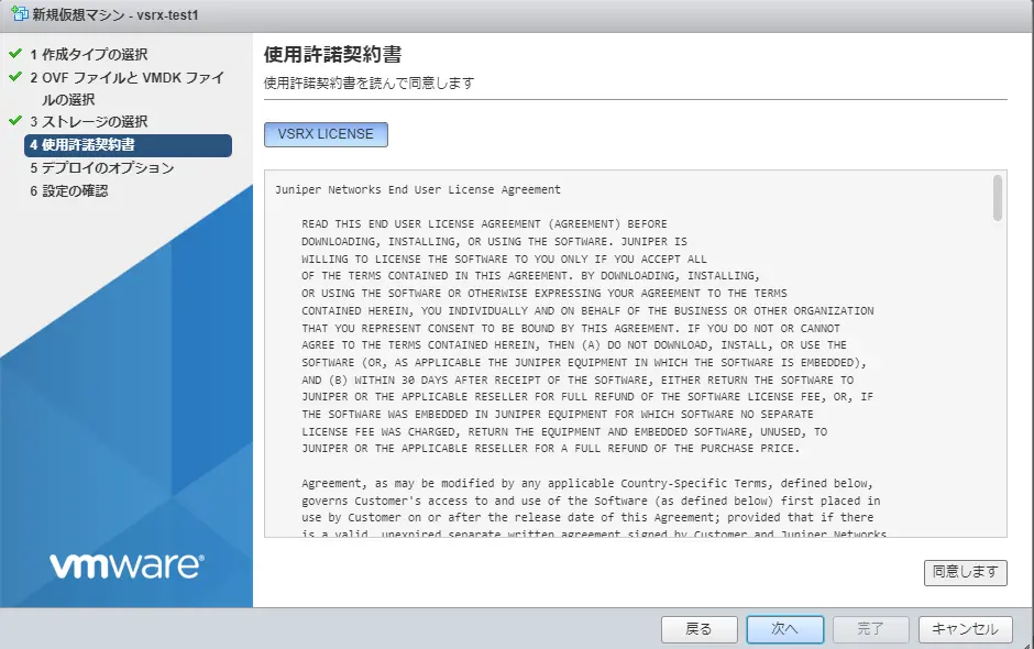
使用許諾契約書に同意します。
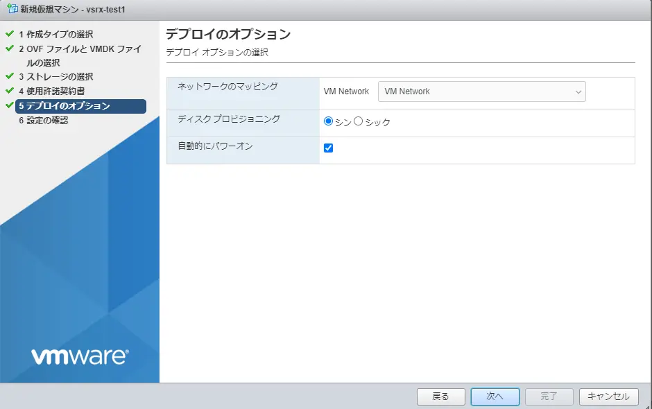
デプロイのオプションもデフォルトのまま次へ進みます。
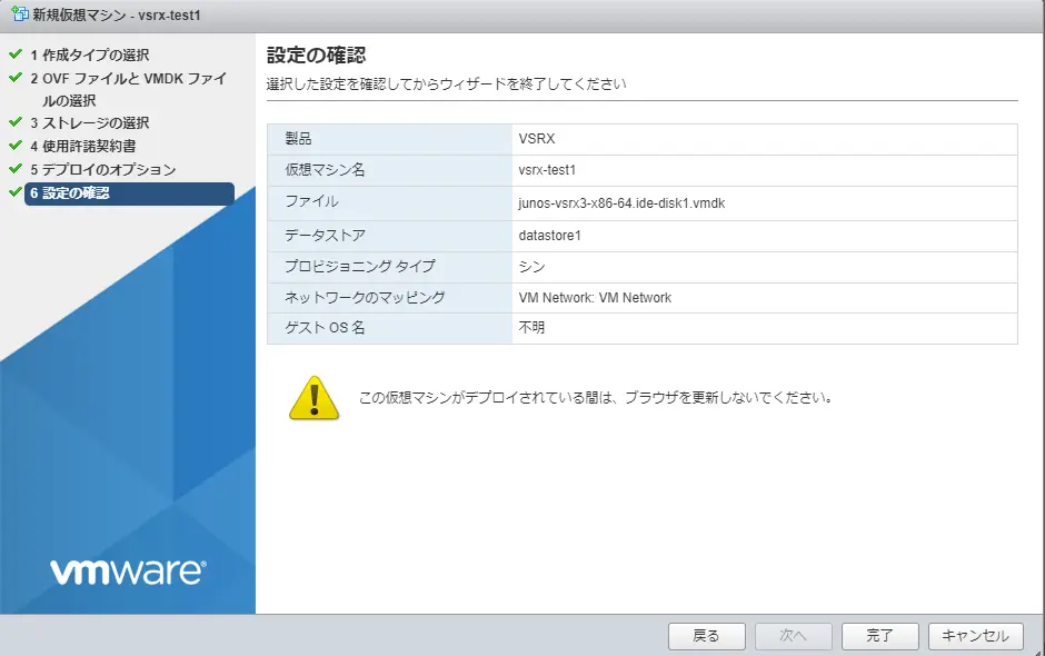
設定内容を確認し、完了をクリックします。HA(Chassis Cluster)を構成するために、同じ手順でもう1台仮想マシンを作成してください。
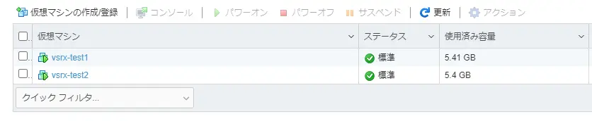
以下のように仮想マシンが2つ作成します。
vSwitchとポートグループの作成
vSwitchとポートグループを作成します。vSwitchは仮想的なスイッチで、ポートグループは仮想マシン(VM)との通信に用いられる仮想的なポートです。
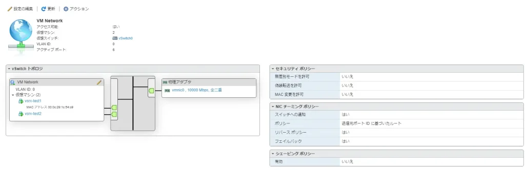
当環境ではデータインターフェース用のvSwitchはデフォルトのvSwitch0で代用しています。
「標準仮想スイッチの追加」からvSwitchを作成します。
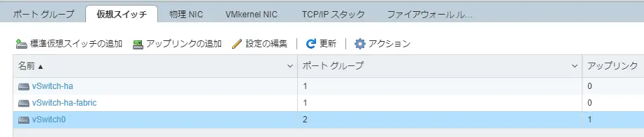
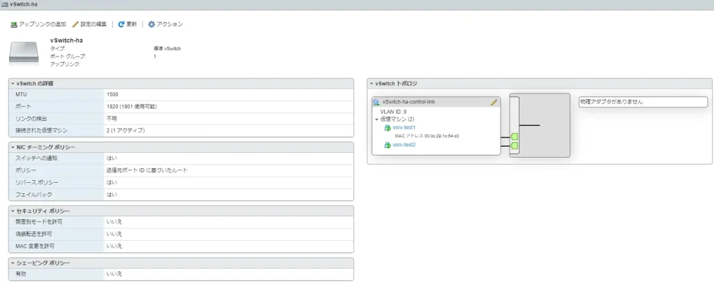
コントロールリンク用のvSwitch設定は以下のとおりです。
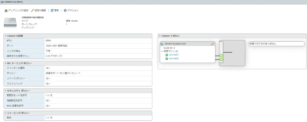
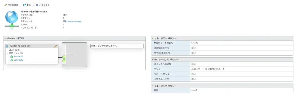
ファブリックリンク用のvSwitch設定は以下のとおりです。
公式のとおり「ポートグループの追加」からポートグループを作成します。
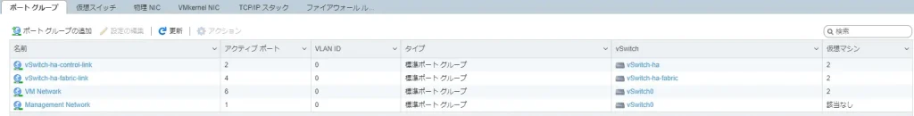
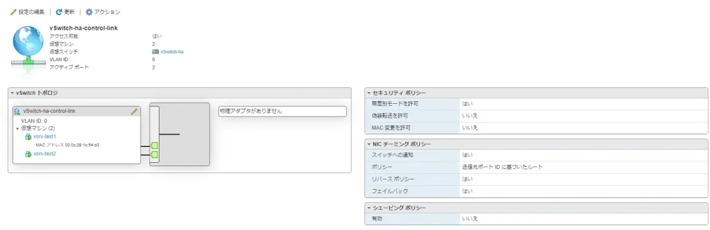
コントロールリンク用のvSwitchに紐づけるポートグループの設定は以下のとおりです。
ファブリックリンク用のvSwitchに紐づけるポートグループの設定は以下のとおりです。
デフォルトのvSwitchに紐づけるポートグループの設定は以下のとおりです。
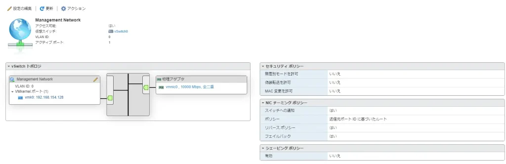
デフォルトの管理用vSwitchに紐づけるポートグループの設定は以下のとおりです。
ネットワークアダプタの追加・設定
vSwitchとポートグループを作成したら、ネットワークアダプタを設定します。公式にあるとおり、スタンドアロンとクラスタを組む場合でネットワークアダプタに割り当てられるインターフェースが異なるので注意してください。
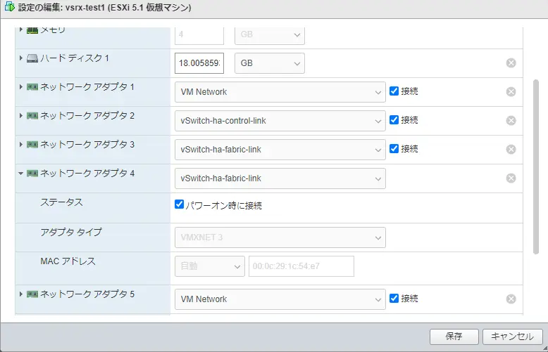
HA(Chassis Cluster)を組む場合は、ネットワークアダプタ2がem0(コントロールリンク)で、ネットワークアダプタ3がファブリックリンクです。今回は、一般的な構成のようにファブリックリンクを冗長化しています。
最終的に以下のようにネットワークアダプタを設定しました。
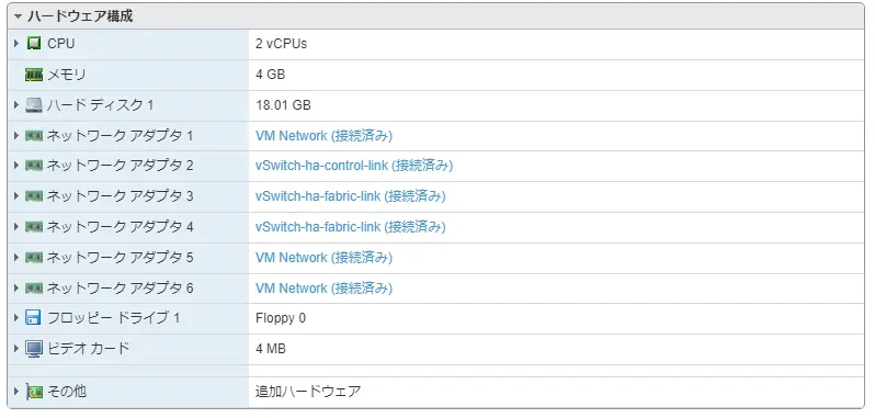
ネットワークアダプタを追加する際は、アダプタタイプを「VMXNET3」を選択してください。
Chassis Cluster設定方法
HAの有効化
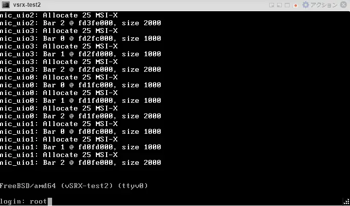
ESXiで作成したvSRXにコンソールログインします。初期アカウントは「root」で、エンターを入力すればログインできます。
ログインしたら、シェルモードからCLIモードに移行し、chassis clusterを有効化して再起動させます。
## シェルモードからCLIモードに移行
cli

## 1号機で実施
set chassis cluster cluster-id 1 node 0 reboot

## 2号機で実施
set chassis cluster cluster-id 1 node 1 reboot
マネジメントIPとSSHの有効化
HAの1号機で、マネジメントIPアドレスの設定とSSHの有効化設定を行います。以降の設定作業は、TeratermなどからSSHログインできるようになり、HAの1号機から設定を行えば、2号機側に設定コンフィグが同期されます。
## 1号機で実施

cli
configure
set groups node0 interfaces fxp0 unit 0 family inet address 192.168.154.2/24
set groups node1 interfaces fxp0 unit 0 family inet address 192.168.154.3/24
set apply-groups ”${node}”
set system services ssh root-login allow
set system root-authentication plain-text-password
show | compare
commit
HA冗長化設定コマンドの投入
HA(Chassis Cluster)冗長化コマンドを設定します。
## 以下1号機から流し込み、同期させる(冗長化設定)

set cli screen-length 0
configure
set groups node0 system host-name vSRX-test1
set groups node1 system host-name vSRX-test2

set interfaces fab0 fabric-options member-interfaces ge-0/0/0
set interfaces fab0 fabric-options member-interfaces ge-0/0/1
set interfaces fab1 fabric-options member-interfaces ge-7/0/0
set interfaces fab1 fabric-options member-interfaces ge-7/0/1


set chassis cluster redundancy-group 0 node 0 priority 200
set chassis cluster redundancy-group 0 node 1 priority 100
set chassis cluster redundancy-group 1 node 0 priority 200
set chassis cluster redundancy-group 1 node 1 priority 100

set chassis cluster reth-count 2
set interfaces reth0 redundant-ether-options redundancy-group 1
set interfaces reth0 unit 0 family inet address 10.0.0.1/24
set interfaces reth1 redundant-ether-options redundancy-group 1
set interfaces reth1 unit 0 family inet address 172.16.0.1/24

set interfaces ge-0/0/2 gigether-options redundant-parent reth0
set interfaces ge-7/0/2 gigether-options redundant-parent reth0
set interfaces ge-0/0/3 gigether-options redundant-parent reth1
set interfaces ge-7/0/3 gigether-options redundant-parent reth1
show | compare
commit
HAステータス確認
HA(Chassis Cluster)のステータス確認コマンドは3つが有用です。
## HA(Chassis Cluster)のステータス確認

show chassis cluster status
show chassis cluster interfaces
show interfaces terse
show chassis cluster status
Chassis Clusterが想定通りに設定されているかを確認します。どちらのRedundancy groupでもnode0(1号機)がプライオリティ200でprimaryであることを確認します。
root@vSRX-test1> show chassis cluster status
Monitor Failure codes:
    CS  Cold Sync monitoring        FL  Fabric Connection monitoring
    GR  GRES monitoring             HW  Hardware monitoring
    IF  Interface monitoring        IP  IP monitoring
    LB  Loopback monitoring         MB  Mbuf monitoring
    NH  Nexthop monitoring          NP  NPC monitoring
    SP  SPU monitoring              SM  Schedule monitoring
    CF  Config Sync monitoring      RE  Relinquish monitoring
    IS  IRQ storm
Cluster ID: 1
Node   Priority Status               Preempt Manual   Monitor-failures
Redundancy group: 0 , Failover count: 1
node0  200      primary              no      no       None
node1  100      secondary            no      no       None
Redundancy group: 1 , Failover count: 1
node0  200      primary              no      no       None
node1  100      secondary            no      no       None
{primary:node0}
root@vSRX-test1>
show chassis cluster interfaces
コントロールリンク(em0)、ファブリックリンク(fab0、fab1)、冗長化インターフェース(reth0、reth1)がUPしていることを確認します。
root@vSRX-test1> show chassis cluster interfaces
Control link status: Up
Control interfaces:
    Index   Interface   Monitored-Status   Internal-SA   Security
    0       em0         Up                 Disabled      Disabled
Fabric link status: Up
Fabric interfaces:
    Name    Child-interface    Status                    Security
                               (Physical/Monitored)
    fab0    ge-0/0/0           Up   / Up                 Disabled
    fab0    ge-0/0/1           Up   / Up                 Disabled
    fab1    ge-7/0/0           Up   / Up                 Disabled
    fab1    ge-7/0/1           Up   / Up                 Disabled
Redundant-ethernet Information:
    Name         Status      Redundancy-group
    reth0        Up          1
    reth1        Up          1
Redundant-pseudo-interface Information:
    Name         Status      Redundancy-group
    lo0          Up          0
{primary:node0}
root@vSRX-test1>
show interfaces terse
物理IF(ge-0/0/1など)、コントロールリンク(em0)、ファブリックリンク(fab0、fab1)、冗長化インターフェース(reth0、reth1)がUPしていることを確認します。
root@vSRX-test1> show interfaces terse
Interface               Admin Link Proto    Local                 Remote
ge-0/0/0                up    up
ge-0/0/0.0              up    up   aenet    --> fab0.0
gr-0/0/0                up    up
ip-0/0/0                up    up
lt-0/0/0                up    up
ge-0/0/1                up    up
ge-0/0/1.0              up    up   aenet    --> fab0.0
ge-0/0/2                up    up
ge-0/0/2.0              up    up   aenet    --> reth0.0
ge-0/0/3                up    up
ge-0/0/3.0              up    up   aenet    --> reth1.0
ge-7/0/0                up    up
ge-7/0/0.0              up    up   aenet    --> fab1.0
ge-7/0/1                up    up
ge-7/0/1.0              up    up   aenet    --> fab1.0
ge-7/0/2                up    up
ge-7/0/2.0              up    up   aenet    --> reth0.0
ge-7/0/3                up    up
ge-7/0/3.0              up    up   aenet    --> reth1.0
dsc                     up    up
em0                     up    up
em0.0                   up    up   inet     129.16.0.1/2
                                            143.16.0.1/2
                                   tnp      0x1100001
fab0                    up    up
fab0.0                  up    up   inet     30.17.0.200/24
fab1                    up    up
fab1.0                  up    up   inet     30.18.0.200/24
fti0                    up    up
fxp0                    up    up
fxp0.0                  up    up   inet     192.168.154.2/24
gre                     up    up
ipip                    up    up
irb                     up    up
lo0                     up    up
lo0.16384               up    up   inet     127.0.0.1           --> 0/0
lo0.16385               up    up   inet     10.0.0.1            --> 0/0
                                            10.0.0.16           --> 0/0
                                            128.0.0.1           --> 0/0
                                            128.0.0.4           --> 0/0
                                            128.0.1.16          --> 0/0
lo0.32768               up    up
lsi                     up    up
mtun                    up    up
pimd                    up    up
pime                    up    up
pp0                     up    up
ppd0                    up    up
ppe0                    up    up
reth0                   up    up
reth0.0                 up    up   inet     10.0.0.1/24
reth1                   up    up
reth1.0                 up    up   inet     172.16.0.1/24
st0                     up    up
st0.16000               up    up
tap                     up    up
{primary:node0}
root@vSRX-test1>
まとめ
最後にまとめます。
- ESXi上でvSRXのHA(Chassis Cluster)構成を構築可能
- ESXi上で構築する場合、スタンドアロンとクラスターでネットワークアダプタが異なるので注意
以上!